

Ship bow wave simulations
2D+T simulation
Converts a steady 3-D problem into an unsteady 2-D problem
Transforms streamwise distance x into time t via the transformation x = x0 + ct where c is ship speed
Assumes slender body (length/beam ≈ 10 and fine bow )
2D+T wave maker – wave board follows shape of transverse cut of hull
![]()
Click image to enlarge
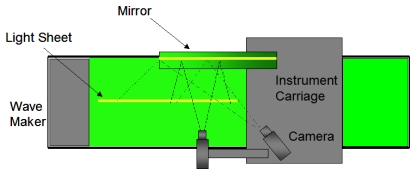
Plan view of photographic system
•The carriage moves with top drive plate.
•The light sheet is oriented along the center-plane of the tank and moves with carriage.
•The high-speed cameras look down and forward at an angle of about 30 degrees from plane of light sheet.
•Resolution about 1 pixel per mm.
•512-by-512 pixel images.
•Total field of view is 79 cm.
•Photographs at 256 pictures per second.
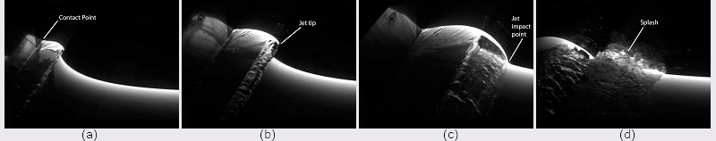
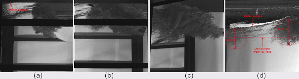
LIF images from a high-speed movie of the wave formation process at four different times for an equivalent ship speed of 27:5 knots. The times for each images are (a) 0.346 s, (b) 0.458 s, (c) 0.578 s, and (d) 0.763 s, corresponding to (a) 0:170Twm, (b) 0:225Twm, (c) 0:280Twm, and (d) 0:375Twm, where Twm = 2:036 s is the time for the 2D+T wave maker to change from the shape at the stem (a °at vertical wall) to the shape at mid ship. These images were taken in a reference frame that is nearly fixed with respect to the top drive channel (located 15.24 cm above the mean water level) of the wave board. The reflection of the wave profile on the wave board can be seen to the left of the contact point of the water surface on the wave board in each image.
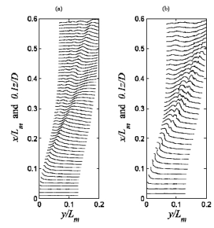
Profile histories of the divergent bow waves generated by the 2D+T wave maker at equivalent ship speeds of 16.5 knots (a) and 27.5 knots (b). Each wave profile is a plot of local dimensionless water surface height (0.1z=D) versus cross stream distance y/Lm at a streamwise distance given by the 2D+T approximation x/Lm =Ut/Lm.
In order to make qualitative observations of the air entrainment process, movies were taken with the high speed camera looking under the free surface through the clear side walls of the wave tank. The camera is looking up toward the free surface from below. The most important features seen in the air entrainment process are two clouds of bubbles under the free surface after the jet impacts the forward face of the wave and the splash forms. The cloud closest to the wave maker (the left cloud of bubbles figure(a)) is due to air entrapped by the plunging jet and the other cloud results from the impact of the splash. The cloud from the splash moves away from the wave maker at a higher speed than the cloud due to the plunging jet; therefore, the separation between the clouds increases as time goes on, see figures (b), (c) and (d).
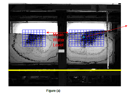
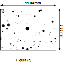
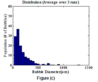
Figure (a):A sample white light image for 27.5 knots 3.15 seconds after starting the wave maker. Figure (b) shows a sample shadowgraph image pair for the above conditions at 146 in away from the wave board and 8 cm below the calm water surface. These images and images taken 2 ms later were processed to obtain bubble size distributions and motions. In figure (c) the bubble diameter distribution (average over three runs) is presented.